¶ GPI Connections from Grand and Solid Servers
¶ Electrical Specs
This module has four general-purpose digital inputs, those inputs can be configured as dry or wet contact.
¶ Select the GPI mode
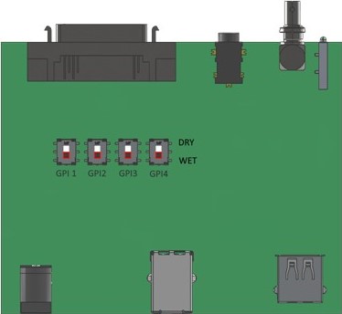
The GPIs mode can be configured between Dry or Wet, by default, all Inputs are configured in WET mode. Each GPI can be configured individually as DRY or WET. To change the mode, you need to open the shell using a Torx #10 screwdriver and find the desire GPI mode switch. The below picture illustrates the position of the switch.

¶ Wet Contact
The Wet contact input consists of an Opto-diode with VF@1.1V in series with a 560 Ohm resistor. The Typical switching point is at 1.1mA, the recommended operation is:
- To HIGH level (Opto ON):
- Voltage from 4 to 25V [GPI(-) on GND and TTL/CMOS signal to GPI(+)]
- Current from 7 to 43mA
- Max current is 43mA
- Max voltage is 25V
- To LOW level (Opto OFF):
- Voltage from 0 to 1.1V [GPI(0) on GND and TTL/CMOS signal to GPI(+)]
- Current from 0 to 0.6mA
¶ Dry Contact
The Dry contact consists in join or closes the GPI(-) to the GPI(+). Please note it needed a prior configuration on the switch mode.
- To HIGH level (Opto ON):
- The input is open
- To LOW level (Opto OFF):
- Close the GPI(-) to the GPI(+)
¶ Connector Pinout
The socket is a conventional 8-pin RJ45 connector with the following pinout:

¶ Hardware Configuration
The configuration of the GPIO module is performed using the Peripheral GPIO tool. This tool is used to configure just the hardware portion of the GPIO and is completely independent of the MOG software.
To use the tool to configure and test the GPIO module executes the Peripheral GPIO tool. The tool is present on the “MOG Support” folder on the MOG desktop.

¶ Configure GPI
The I/Os available to work as inputs are the 1_A, 2_A, 3_A, and 4_A.
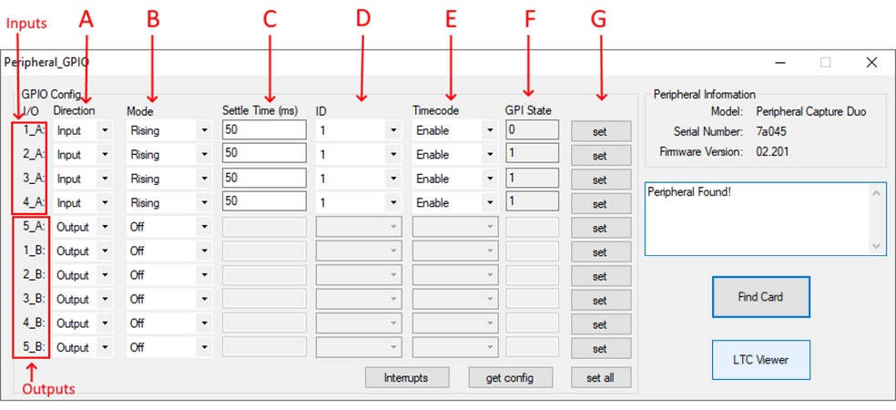
To configure a GPI, you need to configure how the signal is received and how the software will act. First, press the “Find Card” button, then the current configuration will be shown on the GPIO Config panel. To configure it:
- A: the I/O to be used must be selected as “Input” on the “Direction” column;
- B: the input trigger “Mode” is used to select how the event will be detected:
- Rising mode: the event will be triggered when the signal level changes from LOW to HIGH;
- Falling mode: the event will be triggered when the signal level changes from HIGH to LOW.
- C: the “Settle Time” (in milliseconds) to allow an input to settle into its current state;
- D: the ID is the identification number that will be mapped to the event, you can put the same ID for different I/O events. This ID must match the configured ID on the server GPI “.xml” file (see Software Configuration page);
- E: the “Timecode” flag is used to enable the matching of the event with its LTC timecode;
- F: the I/O current status (0 if it is in a LOW state or 1 if it is in a HIGH state);
- G: the configuration can be saved for each modified I/O by pressing their respective “Set” button. The “Set All” button can be used to save all the I/Os’ configurations.
The GPI module detects transitions and triggers events based on it. For instance, if the sender sends a LOW-HIGH-LOW signal impulse, the GPIO module will signal to the host that a valid event as occurred if the signal switches from LOW to HIGH, and stays HIGH for at least 50 ms (this time is configurable on the “Settle Time” setting).
The continuous, or long signal, impulses are managed in the same way, the only difference being that the event triggers are sent every time a transition happens.
All the configurations made on the GPIO are persistent and can be modified later if any adjustment is needed.
After configuring the hardware preferences, you can check if the signals are being received or sent correctly. To check each component:
- Event triggers: press the “Interrupts” button and see the events of the GPI Inputs
- Input current status: press the “Get config” button
- LTC timecode: press the “Read LTC” button
¶ Software Configuration
¶ Configure GPI
The peripheral module will be able to receive interrupts from the GPIO module when a transition is detected in the GPI channels. The event will have the respective timecode and the ID of the GPI input. All actions can be assigned to these transitions using an “.xml” file stored in “%ProgramData%\MOG\MAM4PRO\gpio\Tasks.xml” with a syntax like the following example:
<?xml version="1.0" encoding="utf-8"?>
<Tasks>
        <!--Task that will be executed when the GPI specified by id is signaled-->
    <Task id="1">
    		<!--Inserts a locator on sCapture when the GPI signal is received-->
        <CaptureLocator>
        		<!--Name/Value of the locator-->
            <Name>CAM 1</Name>
        		<!--User name to be associated with the locator-->
            <User>Deck</User>
        		<!--Locator color-->
            <Color>red</Color>
        		<!--List separated by a comma, semicolon or white-space of the sCapture channels that will receive the Locator-->
            <Channels>0;1;2;3</Channels>
        </CaptureLocator>
    </Task>
    <Task id="2">
        <CaptureLocator>
            <Name> CAM 2</Name>
            <User>Deck</User>
            <Color>green</Color>
            <Channels>0;1;2;3</Channels>
        </CaptureLocator>
    </Task>
    <Task id="3">
        <CaptureLocator>
            <Name> CAM 3</Name>
            <User>Deck</User>
            <Color>blue</Color>
            <Channels>0;1;2;3</Channels>
        </CaptureLocator>
    </Task>
</Tasks>