¶ GPO Connections from Grand and Solid Servers
¶ Electrical Specs
As for electrical specs, each GPO connector has 3 solid-state relay ports per connector. Internally it is protected by Opto-isolated Outputs which are bidirectional. Each relay port has a rated maximum of 1A and 40V. There is a GND and a 12V fused 1A line for auxiliary connections if needed.
¶ Connector Pinout
The socket is a conventional 8-in RJ45 connector with the following pinout:

¶ Hardware Configuration
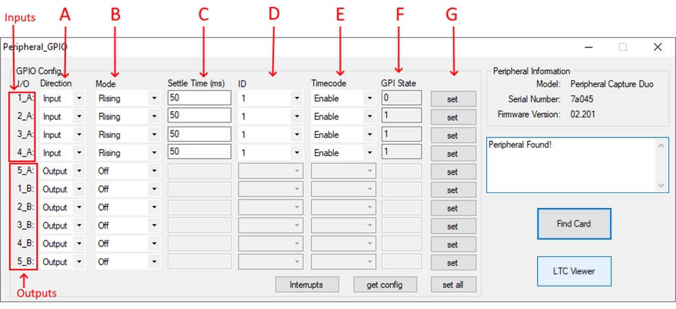
The configuration of the GPIO module is performed using the Peripheral GPIO tool. This tool is used to configure just the hardware portion of the GPIO and is completely independent of the MOG software.
To use the tool to configure and test the GPIO module executes the Peripheral GPIO tool. The tool is present on the “MOG Support” folder on MOG desktop.

¶ Configure GPO
On the GPIO module, the ports are configured as output and turned off by default.
To test the outputs, you just need to modify the I/O “Mode” column to ON and press the “Set” button on the respective GPO line.
Available GPO addresses:
- GPIO1_B: its the physical GPO 1
- GPIO2_B: its the physical GPO 2
- GPIO3_B: its the physical GPO 3
- GPIO4_B: its the physical GPO 4
There are 4 different modes:
- ON: the output is set to HIGH continuously
- OFF: the output is set to LOW continuously
- BLINK: the output alternates between LOW-HIGH each second
- BLINK FAST: the output alternates between LOW-HIGH twice per second
¶ Software Configuration
¶ Configure GPO
The server has a dedicated GPO configuration file for each output event.
The events should be configured on a “.xml” file located at “%ProgramData%\MOG\MAM4PRO\gpio\Events.xml”.
The following “Events.xml” needs to be configured:
<?xml version="1.0" encoding="utf-8"?>
<Events>
        <!--Events that will trigger GPO actions when something happens-->
    <Event id="1">
        <!--Listens to changes on the state of sCapture channel 0-->
        <CaptureStateChange channel="0">
            <!--Changes a GPO State when a sCapture recording ends-->
            <Change state="Initialized">
                <Gpo address="GPO_1_B" operation="Off"/>
            </Change>
            <Change state="Capturing">
                <Gpo address="GPO_1_B" operation="On"/>
            </Change>
        </CaptureStateChange>
    </Event>
</Events>
Available GPO addresses:
- GPIO1_B: its the physical GPO 1
- GPIO2_B: its the physical GPO 2
- GPIO3_B: its the physical GPO 3
- GPIO4_B: its the physical GPO 4
Possible states that can be used for events:
- Idle
- Initialized
- Starting
- Capturing
- Stopping
- Shutting_down
Possible GPO Operations:
- Off
- Blink
- Blink_fast
- On